

Todos los productos
-
aislador de la resina de epoxy
-
Aisladores medios del voltaje
-
Aislador de alto voltaje de la resina de epoxy
-
Interruptor de circuito de vacío
-
Buje de la resina de epoxy
-
Componentes eléctricos del dispositivo de distribución
-
transformador de la resina del molde
-
Interruptor de puesta a tierra
-
Contactos eléctricos de cobre
-
Interruptor de alto voltaje de la desconexión
-
Pararrayos del óxido de cinc
-
Bridas de plástico industriales
-
Tubo eléctrico del plástico del conducto
-
Indicadores de alto voltaje
-
disyuntor moldeado del caso
-
interruptor del triturador de la carga
-
Transformador de la distribución de poder
-
 StephanQiuPu es una gran fábrica de la energía eléctrica. le satisfacemos mucho. ¡cooperará con usted otra vez!
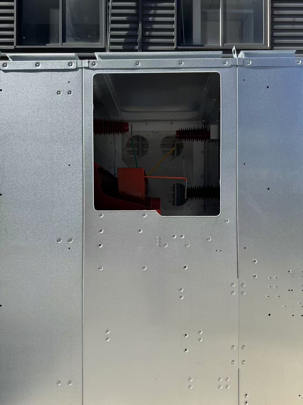
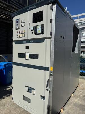
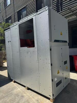
36kV Armored Removable AC Metal Enclosed Switchgear Power Distribution


Datos del producto
| Lugar de origen | Zhejiang, China | Número de modelo | KYN61 |
|---|---|---|---|
| Nombre del producto | Aparamenta cerrada de metal de CA de alto voltaje | Tensión nominal | 40.5kv |
| Grado de protección | Peso de las máquinas | Frecuencia nominal | 50Hz |
| Corriente nominal | 1250,1600,2000,2500A,3150A,4000A |
Descripción de producto
36kV Armored Removable AC Metal Enclosed Switchgear Power Distribution
Product description
KYN61-40.5 armored removable AC metal-enclosed switchgear (hereinafter referred to as switchgear) three-phase AC 50Hz, rated voltage 40.5kV indoor complete power distribution device. As power plants, substations, and industrial and mining enterprises to receive and distribute electric energy, it can control, protect and monitor circuits, and can also be used in places with frequent operations.
This switchgear complies with GB3906-2006 "3~35kV AC Metal-enclosed Switchgear", GB/T11022-1999 "High Voltage Switchgear and Control Equipment Standard Common Technical Requirements" and DL/T 404-2007 "3.6kV~40.5kV AC Metal-enclosed switchgear and control equipment" and other standards.
Model and its meaning
![]()
①Metal armored switchgear
②Removable
③Indoor
④Design serial number
⑤Rated voltage (kV)
⑥Type of circuit breaker: Z-vacuum; SF6-sulfur hexafluoride
⑦Rated current
⑧Rated short-circuit breaking current (kA)
Scope of application
•Ambient temperature: upper limit +40°C, and the average value measured within 24h does not exceed 35°C, lower limit -10°C; •Altitude: altitude does not exceed 1000m;
•Relative humidity: the daily average value does not exceed 95%, and the monthly average value does not exceed 90%;
•Earthquake intensity: no more than 8 degrees;
• Water vapor pressure: the daily average value does not exceed 2.2kPa, and the monthly average value does not exceed 1.8kPa;
Surrounding environment: a place where there is no fire, explosion hazard, serious pollution, chemical corrosion and severe vibration.
Technical Parameters
| Name | Unit | parameter |
| Rated voltage | kV | 40.5 |
| Rated current | A | 1250 1600 2000 |
| Rated frequency | Hz | 50 |
| Rated short-time withstand current | kA | 20 25 31.5 |
| Rated peak withstand current | kA | 50 63 80 |
| Rated power frequency withstand voltage | kV | 95/lmin |
| Rated lightning impulse withstand voltage | kV | 185 |
| Rated short-circuit duration | s | 4 |
| Protection level | IP3X |
Installation dimension drawing
![]()
![]()
![]()
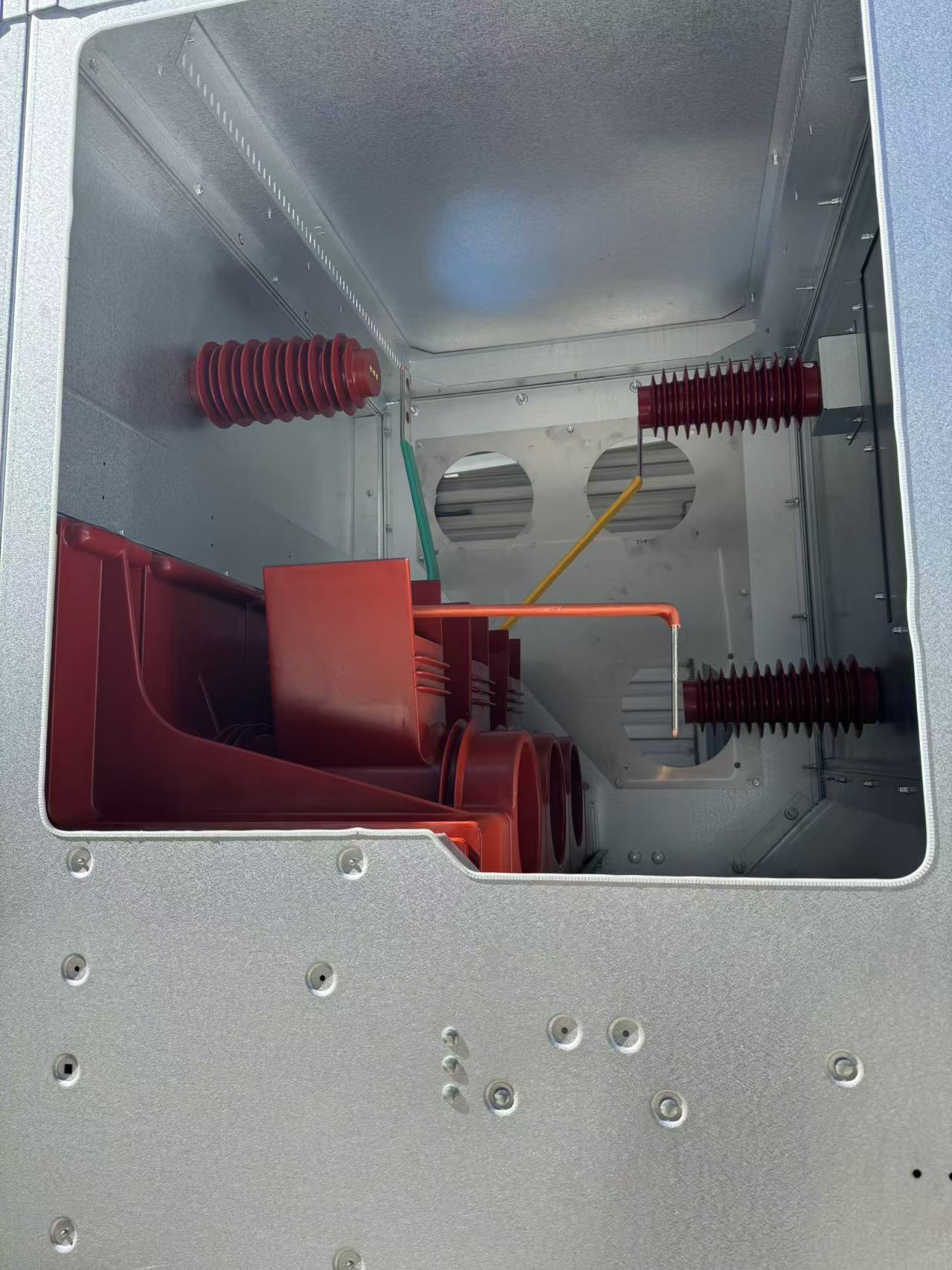
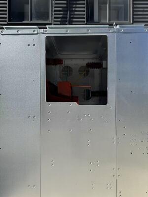
A. Busbar room
B. Handcart room
C. Cable room
D. Relay instrument room
1. Lifting ring
2. Main bus
3. Cover ring for small busbar compartment
4. Instrument room door
5. Branch bus
6. Bus bushing
7. Hornworm head box
8. Analog bus coil
9. Nameplate
10. Lighting
11. Handcart room door
12. Current transformer
13, hairpin chain
14. Insulator
15. Zinc oxide arrester
16. Insulating partition
17. Grounding switch
18. Valve assembly
19. Vacuum circuit breaker handcart
20. Small busbar terminal room
Need to know when ordering
Users need to provide the following information if ordering
• The main circuit plan number, purpose, single-line system diagram, arrangement diagram and power distribution room layout diagram, etc.;
• Auxiliary circuit wiring schematic diagram and terminal arrangement diagram;
• The model, specification and quantity of electrical components in the switchgear;
• Requirements for control, measurement and protection functions of switchgear, as well as requirements for other locking and automatic devices;
• If a bus bridge connection is required between switchgears or incoming cabinets, the rated current carrying capacity of the bus bridge, the span of the bus bridge, the height from the ground and other specific requirements data should be provided; • When accessories and spare parts are needed, the types and quantities should be provided;
• The switchgear is used in special environmental conditions and should be specified when ordering.
Productos recomendados